Computed tomography (CT) is a routine method for the diagnosis of pathological structures in the body and has been widely used in veterinary medicine as an advanced diagnostic imagining tool in veterinary clinics. However, interpretation of CT scans requires detailed knowledge of topographical animal anatomy and usually has limited scan resolution due to the ambiguous relationship between signal intensity and tissue composition. The aim of the study was to assess the morphometric similarities between S10 plastinated slides and computer tomography (CT) scans and their usability as compatible paired diagnostic methods. A 3-year-old euthanized dog cadaver was scanned on SHIMADZU SCT/6800TXL scanner immediately post-mortem, then frozen at -80 °C to preserve the correct anatomical position, and plastinated with a standardized procedure. Semi-transparent transversal slices (5 mm) were obtained from the head, thoracic, and lumbar sections of the body. The S10 plastinated slides and CT scans contained fine and small anatomical structures with high similarity. The spatial relationships of all anatomical structures on the serial S10 platinates were in the correct anatomical position. In conclusion, S10 transversal slices showed high similarity with the CT scans and allowed identification of the corresponding morphological structures. The S10 thin plastinated transversal slices could be used for additional interpretation of CT transversal scans at veterinary clinics and as a didactical tool for veterinary students.
Computed tomography (CT) as a routine method for the diagnosis of diseases in human medicine has been widely used in the last 50 years (
1). In the late 90’s, CT was introduced in veterinary medicine and appeared to be an advanced diagnostic imagining tool in veterinary clinics, since many of the diseases in pet animals can only be diagnosed with the help of CT or magnet resonance scans (
2). However, the interpretations of CT scans or the differentiation of pathological from normal anatomical structures require detailed knowledge of the topographic anatomy of animals (
3). Nowadays, scientists often prefer plastination as one of the most effective tools for easier study of topographic anatomy in animals, especially on thin cross-sectionalized plastinated slices/models, due to the ability to retain the same morphometric characteristics (
3, 4). Many studies have compared thin plastinated slices with CT or magnetic resonance imaging (MRI) (
4, 5, 6). The process of plastination itself proves to be an indispensable tool in the study of animal anatomy, as well as in facilitating the work in clinics, especially for clinical anatomists (
7). In clinical practice, plastination, especially plastinated thin slices, can be used for diagnostic and therapeutic aims in advanced surgery, i.e., surgical anatomy forming a bridge between morphology and clinical practice (
8).
The study aimed to assess the morphometric similarities between S10 plastinated slides and computer tomography (CT) scans and their usability as compatible paired diagnostic methods.
MATERIAL AND METHODS
In this study, we used a 3-year-old euthanized dog cadaver without pathological or anatomical changes. The dog was fixed in the desired position and was placed in dorsal recumbency for taking CT scans. Тhe cadaver’s neck, head, and thoracic limbs were placed in maximal extension in the cranial direction. Тhe hind limbs and the pelvis were positioned in the caudal extension (
5, 9). Auxiliary methods were used to properly position the cadaver by using strips or bands around the limbs and body (
Fig. 1A).
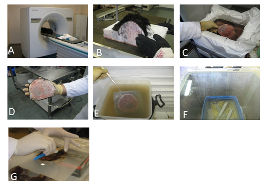 Figure 1.
 Position of the dog for CT imaging (A); Freezing of the dog-cadaver (B); Cutting the dog-cadaver (C); Preparing slices with 5 mm thickness (D); Dehydration stage of plastination (E); Forced impregnation (F); Curing and modeling stage of plastinated slices (G)
A CT scanner SCT SHIMDZU 6800TXL was used at the Animal Hospital “Postojna” in Slovenia. The scans of each section were taken in 5 mm thickness, cranial-caudal direction, without (native) or with a high-pitch resolution for better contrast and differentiation of bones and soft tissues. The images were taken by applying standard protocol (80kV, the effective mA was 100 to 0.5) with a rotation time of 0.6 seconds (
2). They were reconstructed by the B31s algorithm. A 1.2 mm detector was used for reconstructing the 5 mm thickness scans (
Fig. 2).
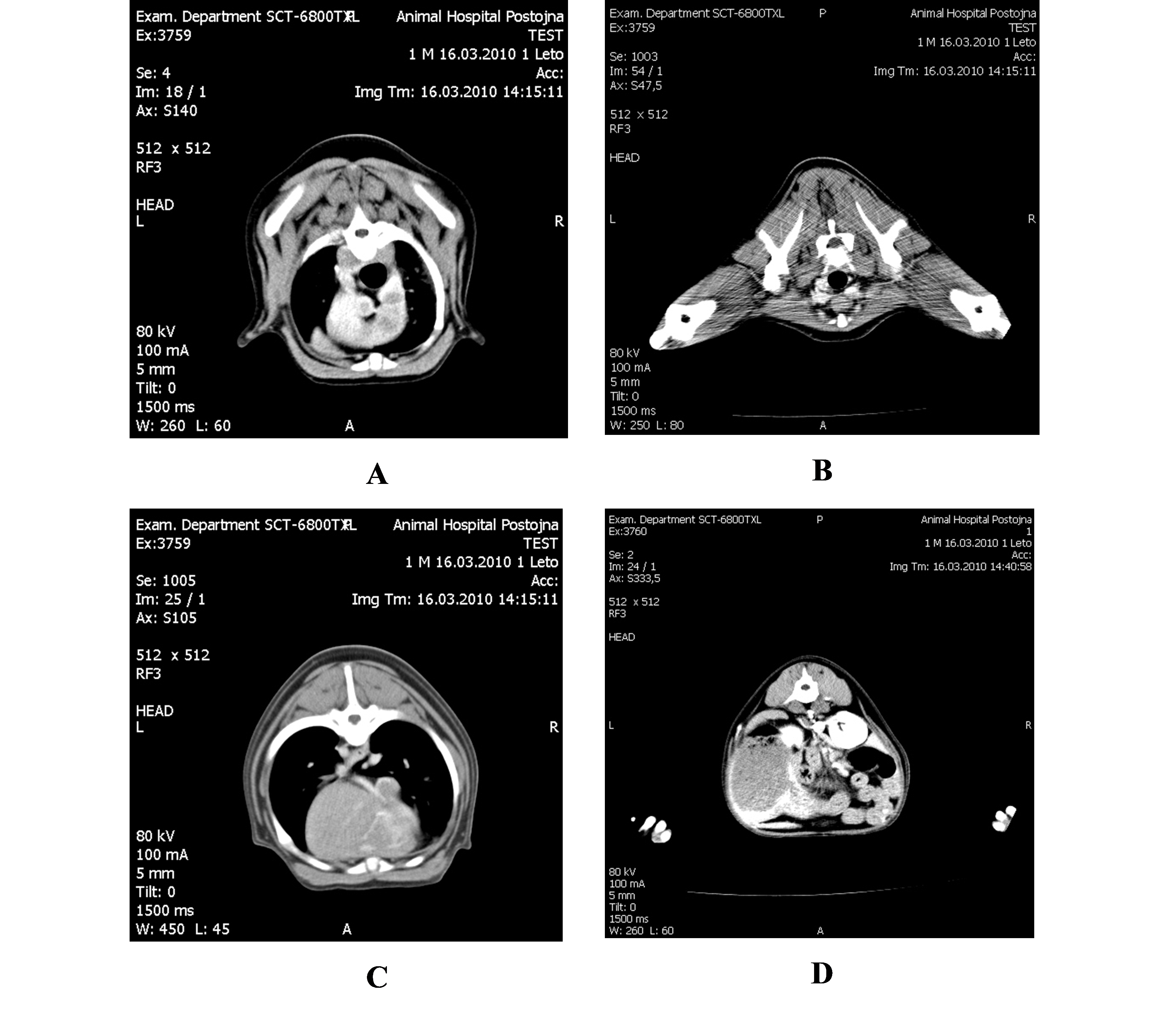 Figure 2.
 CT scans on different levels: Thorax (A); Pelvis (B); Thorax (C); Abdomen (D)
After the CT scan was completed, the dog was immediately frozen at -80 °C (
Fig. 1B) to preserve the correct position needed for obtaining the slices during the plastination. The slicing and plastination were performed according to the method described by Pendovski et al. (
10). The frozen cadaver was cut into four body parts using a band saw. Each body part was immediately returned at -80 °C (
Fig. 1C). Transversal 5 mm slices were cut from the head, thoracic, and lumbar sections of the body (
Fig. 1D). The dehydration process (
Fig. 1E) was performed with cold acetone (-25 °C) in a 10:1 ratio with the slices (
11). The step of forced impregnation (
Fig. 1F) was performed at -25 °C with a mix of silicone (S10 with S3, in a 100:0.5 ratio) (
11). The modeling of the slices was performed with S6 silicone in 5% concentration (
Fig. 1G) (
12).
The plastinated models were photographed (scanned) with the corresponding CT scans’ level/ angle. Comparisons were made on the following anatomical regions: first molar tooth (M1) (sinuses, muscles, glands, bones, globe of the eye, nasal turbinate), second thoracic vertebra (T2) (muscles, blood vessels, bones, organs: esophagus, heart, pericardium, valves), fourth thoracic vertebra (T4) (muscles, blood vessels, bones, organs: esophagus, heart, pericardium, valves), first lumbar vertebra (L1) (muscles, blood vessels, bones, organs: esophagus, heart, pericardium, valves), and fourth lumbar vertebra (L4) (muscles, blood vessels, organs: small and large intestines, kidneys, lymph nodes, lien).
RESULTS
The photographs of plastinated slices and CT scans are presented in Figures 3-7.
The compared anatomical structures (glands, blood vessels, pyloric thickness, major nerves) were highly comparable between the plastinated transverse sections and CT scans. The corresponding structures were equally visible and identifiable in the plastinated slices, CT scan, and native photography.
In M1 region (
Fig. 3) the following anatomical structures were easily recognizable and highly comparable between the three scanned models: bones (zygomatic arc, mandible, maxilla, molar tooth I), muscles (pterygoid, genioglossus, and ventral oblique muscle), cavities (frontal sinus, ethmoidal conchae, oral cavity), zygomatic gland, hard palate, bulbus olfactorius, ocular globe (bulbus oculi). The pterygoid muscle and the zygomatic gland are specific anatomical structures that were highly identifiable (red circles in
Fig. 3).
 Figure 3.
 A. Plastinated slice on level of first molar tooth (M1); B. CT scan (high-pitch); C. CT scan (native): 1. frontal sinus; 2. bulbus olfactorius; 3. ethmoidal conchae; 4. bulbus oculi; 5. zygomatic gland; 6. pterygoid muscle; 7. choana; 8. hard palate; 9. zygomatic arch; 10. mandible; 11. genioglossus muscle; 12. oral cavity; 13. moral tooth I; 14. maxilla; 15. ventral oblique muscle
In the T2 region (
Fig. 4) a large group of chest and back muscles was easily visible (longus colli, spinalis thoracis, multifidus, semispinalis, splenius, ventral serratus, and supraspinatus muscle). In the middle part of
Fig. 4 (A-white and B-red circle) the following anatomic structures were easily recognizable and highly comparable between the three scanned models: organs (lungs, esophagus, trachea), glands (thymus), and blood vessels (cranial vena cava, internal thoracic vein, left subclavian artery, brachiocephalic trunk, and left common carotid artery).
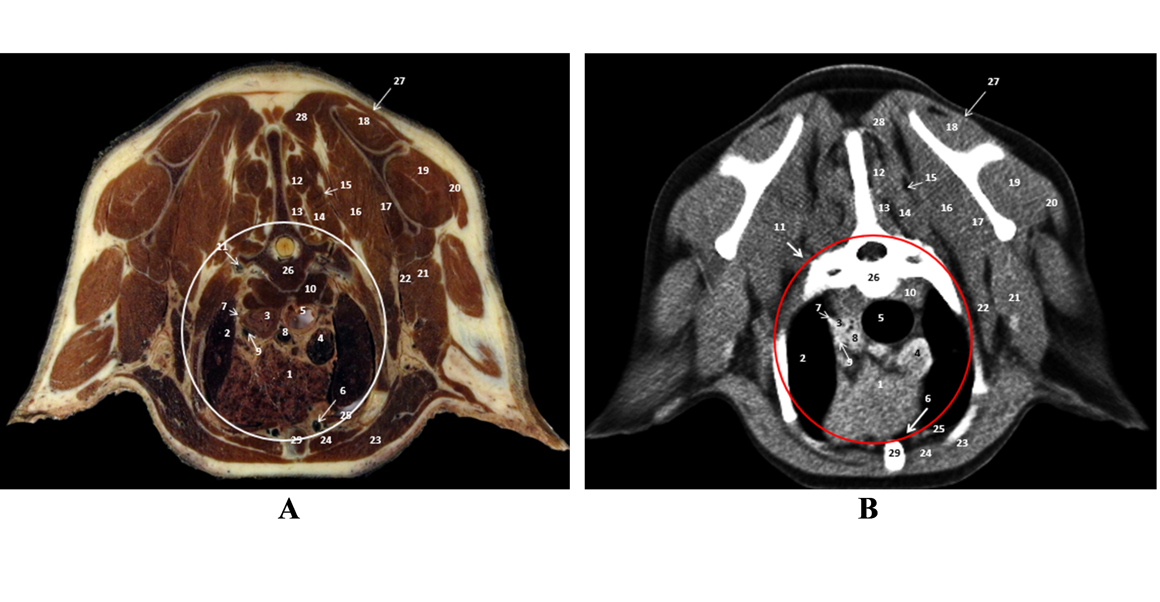 Figure 4.
 A. Plastinated slice level of second thoracic vertebra (T2); B. CT scan (native): 1. thymus; 2. left cranial pulmonic lobe; 3. esophagus; 4. cranial vena cava; 5. trachea; 6. internal thoracic artery and vein; 7. left subclavian artery; 8. brachiocephalic trunk; 9. left common carotid artery; 10. longus colli muscle; 11. vertebral artery; 12. spinalis thoracis muscle; 13. multifidus thoracis muscle; 14. semispinalis capitis muscle; 15. splenius muscle; 16, 17. ventral serratus muscle; 18. supraspinatus muscle; 19. infraspinatus muscle; 20. deltoideus muscle; 21. triceps brachii muscle; 22. teres major muscle; 23. pectoral muscle; 24. rectus thoracis muscle; 25. transversus thoracis muscle; 26. thoracic vertebra II; 27. trapezius muscle; 28. rhomboideus muscle; 29. sternum
In the T4 region, back and chest muscles (trapezius, longissimus, multifidus, latissimus dorsi, iliocostalis, ventral serratus, and deep pectoral muscle) were easily recognizable and comparable (
Fig. 5). In the red circle mark (
Fig. 5A, B, C) the following structures were easily recognizable and highly comparable between the three scanned models: organs (heart and parts of left and right atria and ventricles, pericardium, bicuspid valves, lung lobes, and esophagus), blood vessels (left pulmonic artery, aorta, right azygous vein, thoracic vein, and artery).
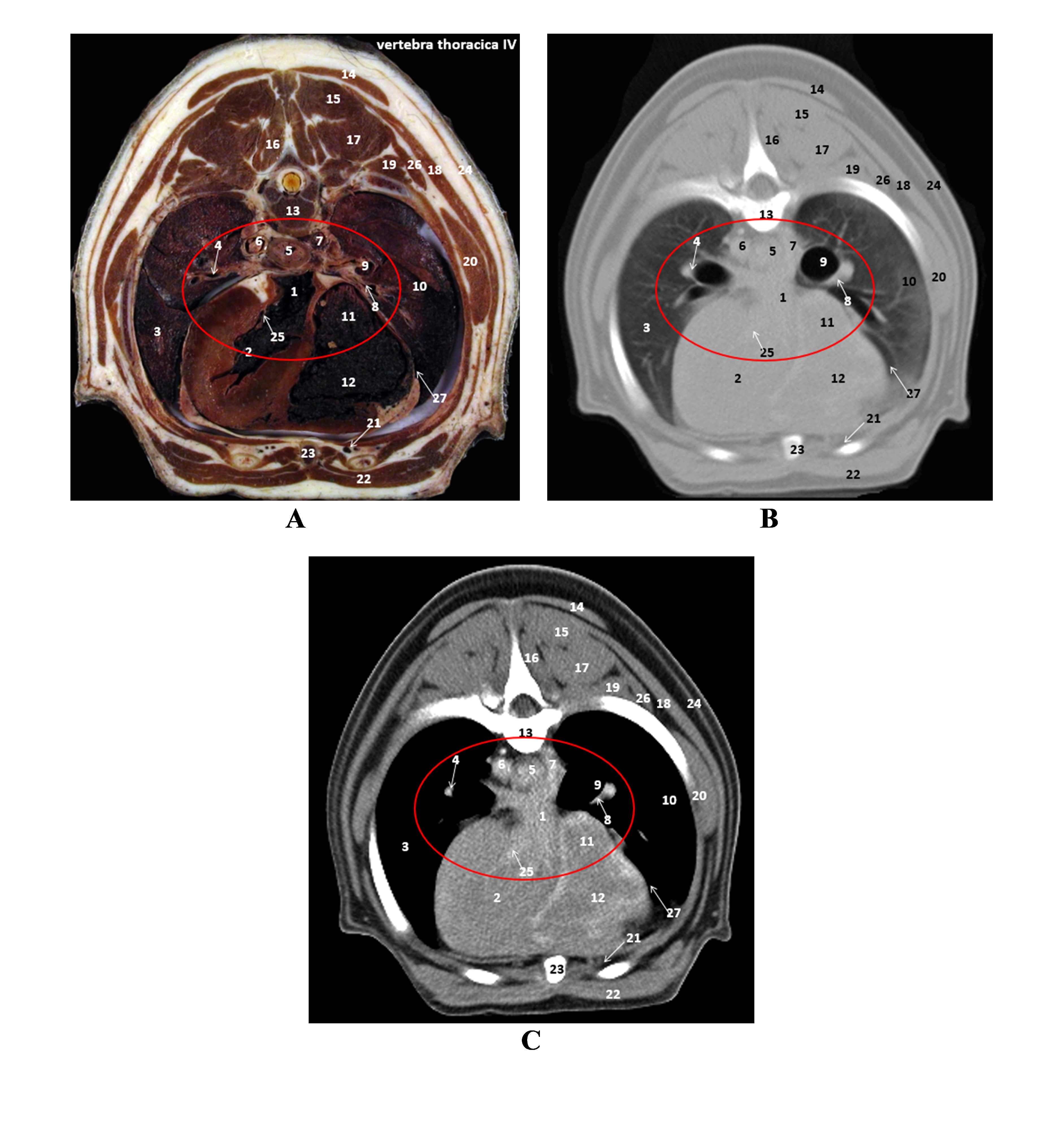 Figure 5.
 A. Plastinated slice level of fourth thoracic vertebra (T4); B. CT scan (high-pitch); C. CT scan (native): 1. left atrial chord; 2. left ventricular chord; 3. left lung; 4. left pulmonic artery; 5. esophagus; 6. aorta; 7. right azygous vein; 8. right pulmonic artery; 9. bronchus; 10. right lung; 11. right atrial chord; 12. right ventricle; 13. fourth thoracic vertebra; 14. trapezius muscle; 15. semispinalis thoracis muscle; 16. multifidus; 17. longissimus dorsi muscle; 18. latissimus dorsi muscle; 19. iliocostalis muscle; 20. ventral serratus thoracis muscle; 21. internal thoracic artery and vein; 22. deep pectoral muscle; 23. sternum; 24. cutaneous trunci muscle; 25. bicuspid valves; 26. cranial dorsal serrate muscle; 27. pericardium
In the L1 region (
Fig. 6A, B, C), the back muscles (multifidus, longissimus, iliocostalis, and quadratus lumborum muscle), organs (stomach with ingested content and pylorus, kidney, small intestine, liver), and blood vessels (aorta, caudal vena cava, and portal vein) were easily recognizable and highly comparable between the three scanned models.
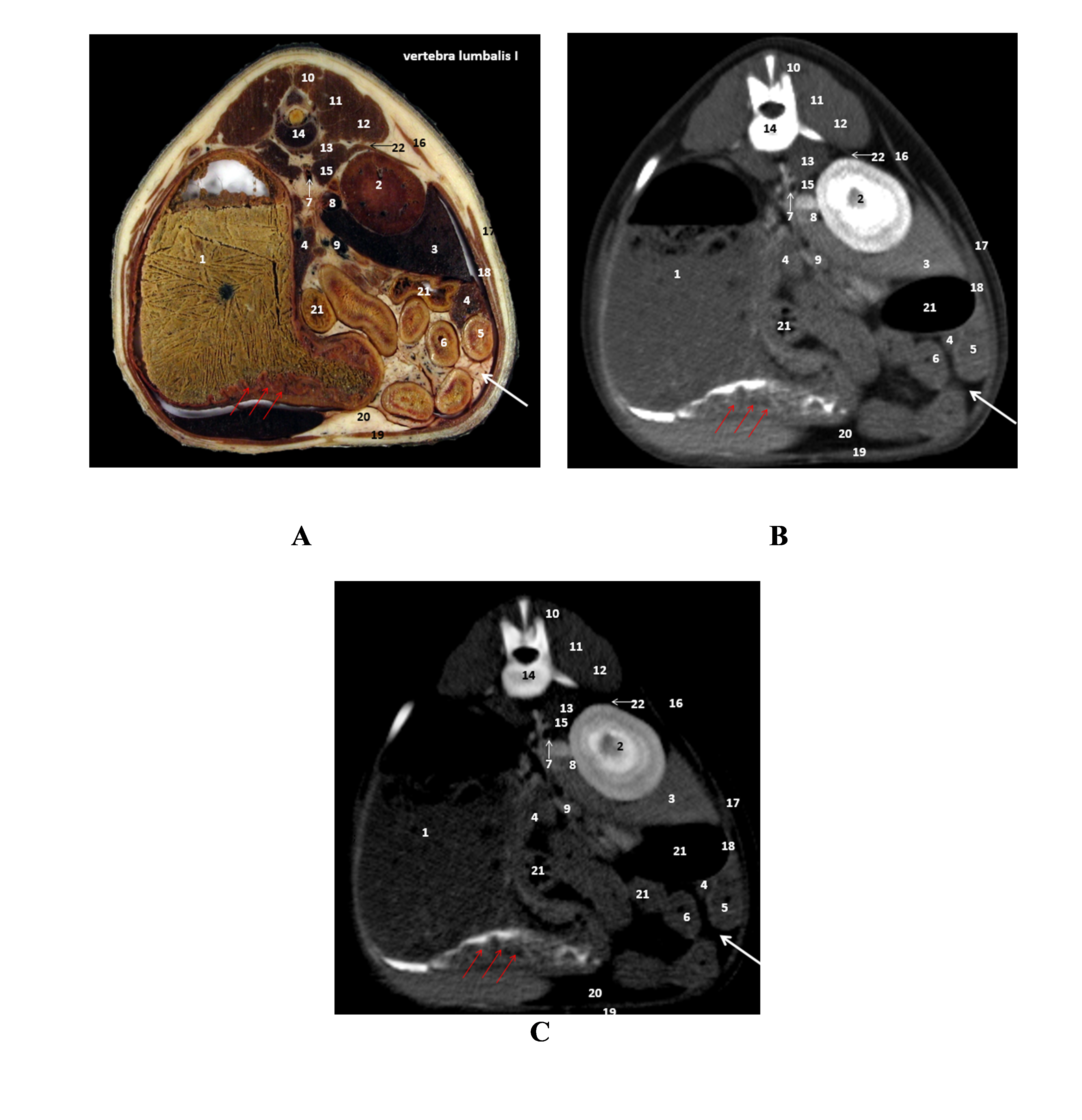 Figure 6.
 A. Plastinated slice level of first lumbar vertebra (L1); B. CT scan (high-pitch); C. CT scan (native): 1. stomach (red arrows-pyloric thickness); 2. right kidney; 3. liver (caudate process); 4. pancreas; 5. duodenum; 6. jejunum; 7. aorta; 8. caudal cava vein; 9. portal vein; 10. multifidus muscle; 11. longissimus muscle; 12. iliocostalis muscle; 13. quadratus lumborum muscle; 14. first lumbar vertebra; 15. psoas muscle; 16. dorsal serratus caudalis muscle; 17. external abdominal oblique muscle; 18. transverse abdominal muscle; 19. rectus abdominis muscle; 20. falciform ligament; 21. colon; 22. diaphragm. Red arrows: stomach with ingested gastric content
In
Fig. 7, the back muscles (quadratus lumborum muscle, multifidus, iliocostalis, longissimus, and psoas major and minor), stomach muscles (external and internal abdominal oblique, rectus abdominis, and transverse abdominis muscle), organs (kidney, small and large intestine, spleen, and pancreas) lymph nodes, and blood vessels (caudal vena cava, renal artery, and aorta) were easily recognizable and highly comparable between the three scanned models.
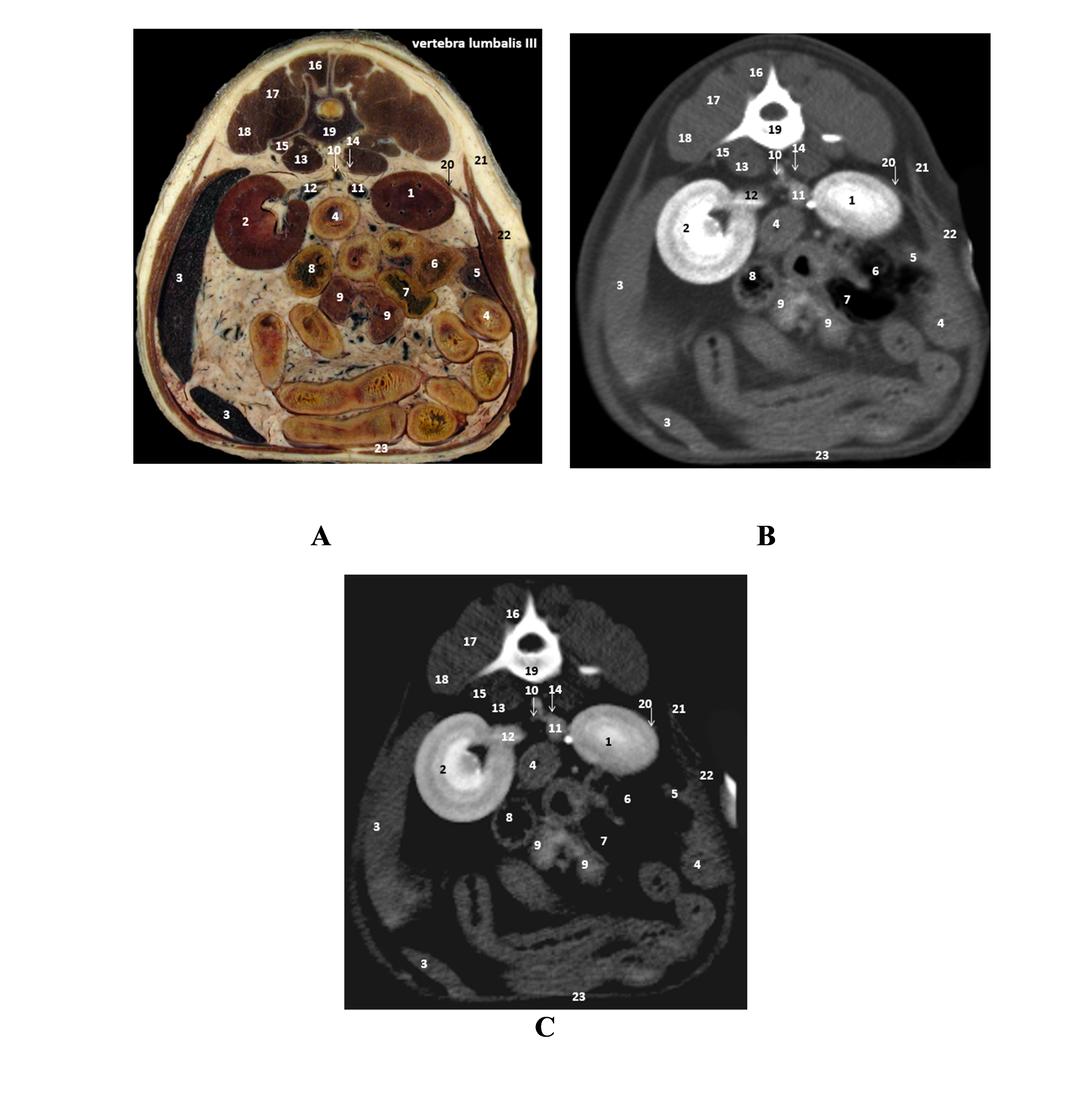 Figure 7.
 A. Plastinated slice fourth lumbar vertebra (L4); B. CT scan (high-pitch); C. CT scan (native): 1. right kidney; 2. left kidney; 3. spleen; 4. duodenum; 5. pancreas; 6. cecum; 7. colon; 8. jejunum; 9. jejunal lymph nodes; 10. abdominal aorta; 11. caudal vena cava; 12. renal artery and vein; 13. psoas major muscle; 14. psoas minor; 15. quadratus lumborum muscle; 16. multifidus muscle; 17. longissimus muscle; 18. iliocostalis muscle; 19. third lumbar vertebra; 20. transverse abdominis muscle; 21. internal oblique abdominis muscle; 22. external oblique abdominis muscle; 23. rectus abdominis muscle
DISCUSSION
CT is an important diagnostic tool in veterinary medicine able to scan and visualize large and fine anatomical structures in the body yielding easier, faster, and more accurate diagnosis (
13). CT is used as an important tool in research and scientific activity contributing to more advanced study designs (
14). CT images usually visualize the body in transverse planes of different thickness. It is also possible to transverse CT images and rearrange them into sagittal or frontal planes using certain software programs contributing to a more accurate and concise diagnosis (
15).
Numerous studies reported that thin plastinated models are a useful tool for pre-training programs for CT and MRI (
3, 6, 16). The plastinated models retain the fine structure and topography of the corresponding native slices with a translucent layer of connective and lipid tissues, rendering arteries and veins easily visible (
17). An important part that makes our study different from the previous studies is that we used thin plastinated models instead of using frozen cadavers (
3, 18).
In this study, the CT scans proved to be a useful tool for comparison of thin plastination models of a dog’s body. Each plastinated slice and correspondent CT scan provided detailed information on the topographic anatomy of the dog cadaver. Our findings are similar with other investigators that preformed similar research (
3, 5, 6, 16, 17). No topographic changes were found in the thin plastinated models compared to the corresponding CT scans. The plastinated models are long-lasting and could replace frozen cadavers which are routinely used for teaching and demonstrating purposes (
3, 18).
CONCLUSION
The S10 plastinated transversal sliced models of dog cadaver successfully reproduced the anatomical and topographic features of the corresponding CT scanned sections. The plastinated models could therefore be used as a didactical and diagnostic tool for veterinary students, practitioners, and researchers.
CONFLICT OF INTEREST
The authors declare that they have no potential conflict of interest with respect to the authorship and/or publication of this article.
ACKNOWLEDGMENTS
The study was conveyed as part of the scientific research project „The Western Balkans University Network for Animal Welfare” (WBVN/RSPCA/2008/01) with RSPCA International. This research was supported by the Faculty of Veterinary Medicine – Skopje.
AUTHORS’ CONTRIBUTION
LP conceived and designed the study, supervised the experiments and data analysis, interpreted the results, performed a major part of the experiments and wrote the manuscript. DB interpreted the results and wrote the manuscript. KI, PT participated in computed tomography interpretations and monitored manuscript writing. VI supervised the study and manuscript writing. All authors have revised and approved the final version of the manuscript.

 10.2478/macvetrev-2022-0020